APPLICATION
Centrifugal Brakes for Zip Lines & Alpine Coasters
Controlled speed for safe thrills – purely mechanical regulation, with no power or electronics required.
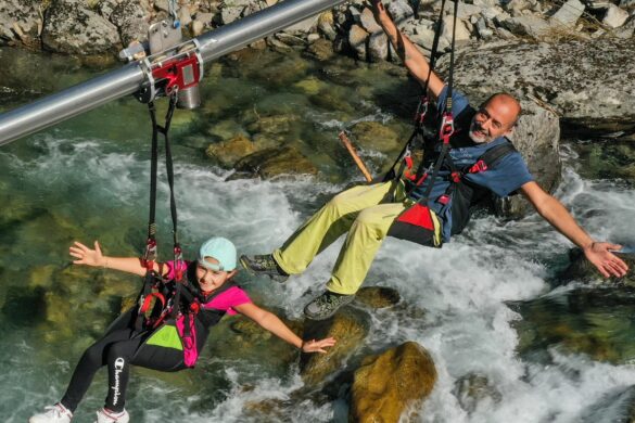
Zip Lines & Flying Fox: Consistent Speed for Every Rider
Whether it's a Flying Fox or a zip line course in a high ropes park – the speed must stay within a safe range regardless of the rider, whether it's a child, an adult, or a mixed group. Our centrifugal brakes reliably limit the maximum speed, with no need to readjust or recalibrate at the platform each time.
What matters for safety: an incorrectly sized brake means an uncontrolled risk of impact at the end of the line. That's why we size every brake individually based on line length, gradient, and maximum rider weight, with a built-in safety margin.
Controlled Cornering Instead of Speed Risk on Alpine Coasters
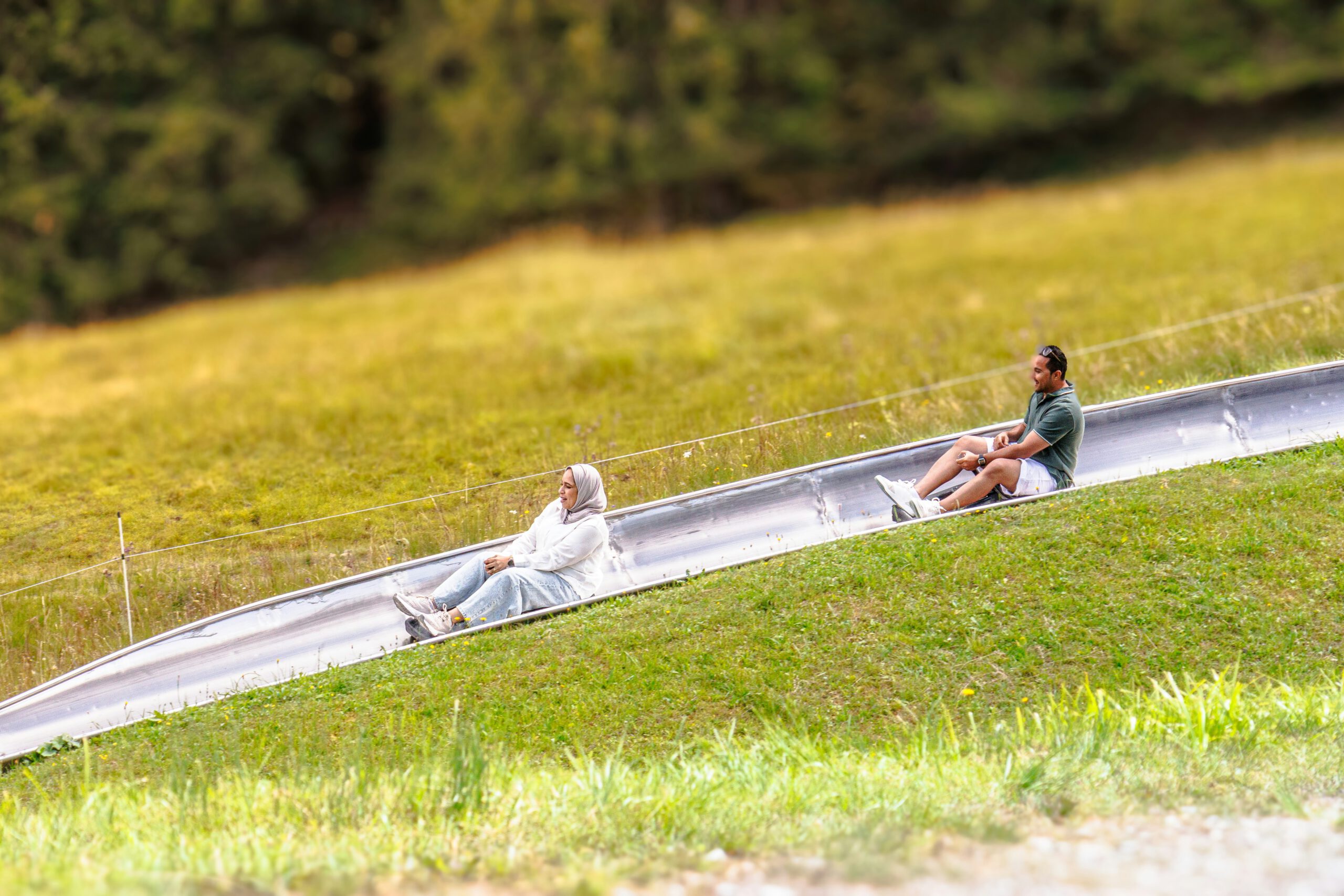
Fast-paced mountain toboggan runs are a draw – especially when families with children mix different riding speeds on the same track. Our centrifugal brakes automatically limit the sled's speed once it exceeds the defined threshold, regardless of how the rider brakes themselves.
Every disruption counts in leisure operation: the brake must also withstand frequent wind, moisture, and cold, as well as continuous daily use, without any loss of performance.
How a Centrifugal Brake Limits Speed
The centrifugal brake limits speed purely mechanically – with no sensors, software, or external power supply required.
We have been applying this principle in safety-critical applications for over 40 years – from elevators to lifeboats. For zip lines and alpine coasters, we bring the same proven technology to the leisure and events sector.
1. Centrifugal Weights
As rotational speed increases, the centrifugal weights move outward.
3. Spring Regulation
Springs set the desired speed at which the braking effect engages.
2. Brake Linings
They press against the fixed brake housing.
4. Automatic Limiting
The speed is automatically kept at the predefined maximum.
The Right Brake Solution for Your Leisure Attraction
These Factors Are Part of the Sizing Process
Every system is different – that's why we calculate the brake sizing individually based on the following parameters.
01. Engagement Speed
The rotational speed at which the brake builds up its defined braking torque.
02. Required Braking Torque
Determines how strongly the brake engages at the safe target speed.
03. Maximum Braking Duration
How long the brake is continuously in use per ride.
04. Cooling Time Between Braking Cycles
The time between two rides available for the brake to cool down.
05. Weather Conditions
Moisture, frost, and temperature affect braking performance.
06. Installation Situation
New construction or retrofit of an existing system.
Häufige Fragen zu Fliehkraftbremsen für Zipline & Sommerrodelbahn
Wie oft muss eine Fliehkraftbremse gewartet werden?
Wir fragen zunächst per Fragebogen die wichtigsten technischen Eckpunkte ab. Danach prüfen wir, welche Baugröße aus unserem Baukastensystem passt und ob bereits geeignete Komponenten existieren. Auf dieser Basis erarbeiten wir einen ersten Konstruktionsvorschlag, den wir mit Ihnen abstimmen, bevor Sie ein Angebot erhalten.
Funktioniert die Bremse auch bei Nässe und Frost?
Ja, sie ist für den Dauereinsatz im Freien ausgelegt und arbeitet zuverlässig bei Wind, Nässe und niedrigen Temperaturen.
Kann die Bremse nachgerüstet werden oder nur bei Neubau?
Das hängt vom Umfang ab: Ist die Anwendung bereits bekannt, kann eine Entwicklung in wenigen Tagen stehen. Bei komplett neuen Anforderungen mit höherem Abstimmungsbedarf kann es einige Wochen dauern.
Wie lange dauert die individuelle Auslegung?
Ja, wir beraten Sie bei jeder Anfrage zur passenden Auslegung. Wir verstehen uns als Problemlöser und begleiten Sie, bis die beste Lösung für Ihre Aufgabenstellung gefunden ist.
How We Work Together
1. Inquiry & Consultation
You tell us the line profile, speed, and operating conditions.
2. Custom Sizing
We calculate the right brake for your system.
3. Made-to-Measure Manufacturing
Every brake is manufactured to your technical specifications.
4. Delivery & Installation
Your brake is delivered on time – ready for installation in your system.

Our Application Areas at a Glance
Centrifugal Brakes & Clutches for Every Application
© copyright 2026 | Amsbeck
150 North Michigan Avenue
35th Floor
Chicago, Illinois 60601